Technical guide · Laser cutting and engraving

How to prepare files for laser cutting

Layers, formats, scale, area engraving, text and the minimum sizes per thickness. The web version of our laser design guide.

1. Choose the material: sheet size and thickness

Before you start, decide which material you will use, or at least its thickness: the final shape depends on it, especially when several parts slot into each other.

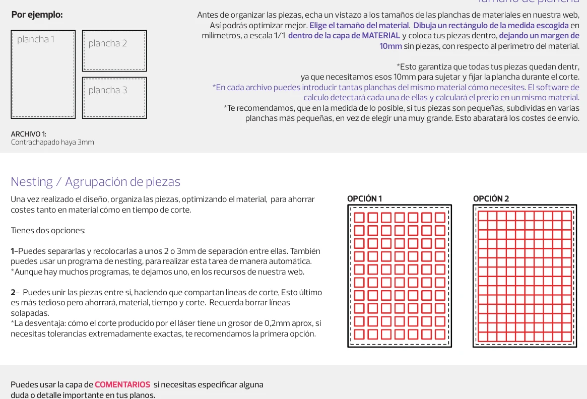
Draw a rectangle with the sheet size in millimetres, at 1:1 scale, on the MATERIAL layer and place your parts inside, leaving a 10 mm margin with no parts around the edge. We need those 10 mm to hold the sheet during cutting.

One file can contain as many sheets of the same material as you need; the quoter detects each one. If your parts are small, several smaller sheets are better than one large sheet: they lower shipping costs.

  • Option 1 – separate parts: leave about 2–3 mm between parts (or use a nesting program).
  • Option 2 – shared lines: parts share cutting lines. It saves material and time, but delete overlapping lines. The laser kerf is about 0.2 mm, so for very tight tolerances choose option 1.
  • Use the COMMENTS layer for any note or important detail.
Original diagram: 1. Choose the material: sheet size and thickness (Spanish labels), 1
Original guide illustration with Spanish labels.

2. How to prepare your design files

Compatible formats: DXF, SVG, EPS, AI, DWG and PDF. Whenever you can, use DXF: it is the most universal and compatible format.

Laser cutting only works with vector design software. Raster images (JPG, PNG…) are not accepted, nor embedded inside vector files: they must be vectorised first. For AI, SVG and PDF files, check the dimensions the quoter detects; the scale can change with the file or program version.

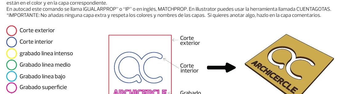
Place each line on its layer/colour depending on whether it is cut, line-engraved or area-engraved. Download our DXF template and use Match Properties (AutoCAD: MATCHPROP / IP) or the Eyedropper (Illustrator) with the template circles. Do not add extra layers or change layer names or colours.

Outer cutRed
Inner cutBlue
Line engraving – strongYellow
Line engraving – mediumGreen
Line engraving – lightCyan
Area engravingMagenta
Sheet (Material)White / grey
CommentsOrange
Original diagram: 2. How to prepare your design files (Spanish labels), 1
Original guide illustration with Spanish labels.

3. Area engraving: what it is and how it works

Besides cutting and line engraving, the laser can engrave a whole closed area like a printer would, removing material and creating a counter-relief. The area must be drawn as CLOSED POLYLINES OR CURVES.

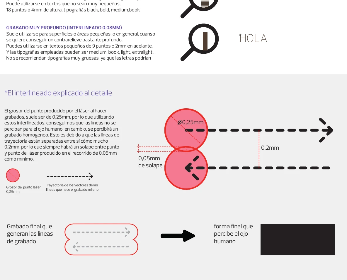
We always use the same power and speed for each material and change the line spacing: more lines give more depth and detail, but take longer. The laser spot is about 0.25 mm, so with spacings of 0.2 mm or less the passes overlap by at least 0.05 mm and the eye sees an even engraving.

Shallow

Line spacing 0.2 mm

Large areas or a subtle engraving. Text from 36 pt or 10 mm in heavy typefaces (black, bold, medium).

Deep

Line spacing 0.12 mm

Medium areas. Text from 18 pt or 4 mm (black, bold, medium, book).

Very deep

Line spacing 0.08 mm

Small areas and a pronounced counter-relief. Text from 9 pt or 2 mm (medium, book, light, extralight). Very heavy typefaces are not recommended.

Original diagram: 3. Area engraving: what it is and how it works (Spanish labels), 1
Original guide illustration with Spanish labels.

4. How to draw vectors for area engraving

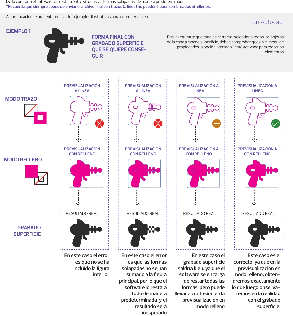
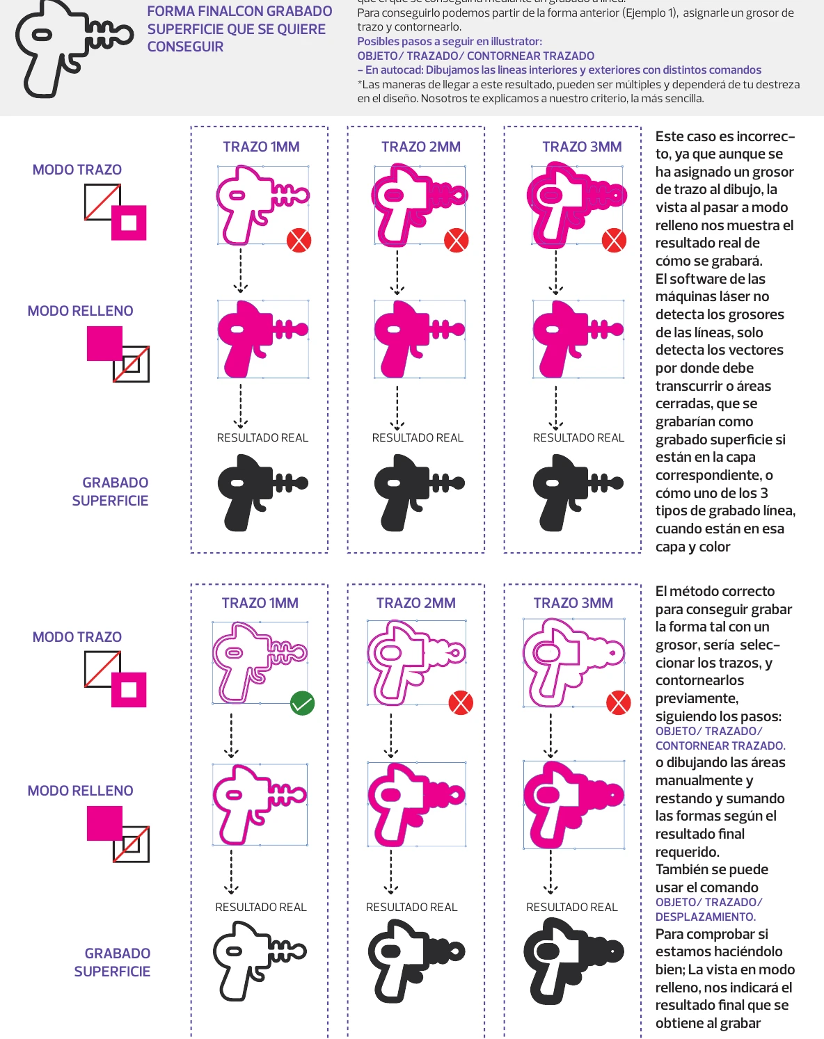
Area engravings must be closed polylines (areas) that can be added to or subtracted from each other. In Illustrator, combine shapes with Pathfinder so they add or subtract as you want; otherwise overlapping shapes are subtracted by default.

Always send the final file as strokes (lines): no shading or fills. To engrave a thick stroke, give it the stroke width and outline it (Object › Path › Outline Stroke). In AutoCAD, draw the inner and outer lines.

Original diagram: 4. How to draw vectors for area engraving (Spanish labels), 1
Original guide illustration with Spanish labels.
Original diagram: 4. How to draw vectors for area engraving (Spanish labels), 2
Original guide illustration with Spanish labels.

5. Engraving text and numbers

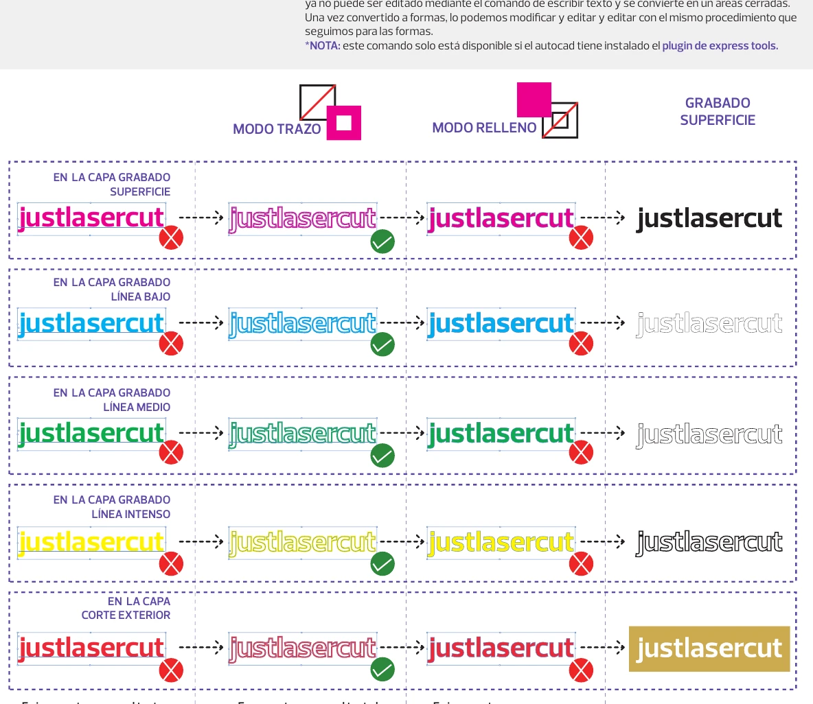
Text must be converted to closed polylines before engraving. In Illustrator: Type › Create Outlines. In AutoCAD: Explode Text (TXTEXP, requires Express Tools).

Fill mode helps you preview the result, but the software cannot read fills: the text must be outlined on the area-engraving layer.

Original diagram: 5. Engraving text and numbers (Spanish labels), 1
Original guide illustration with Spanish labels.

6. Size, units and scale

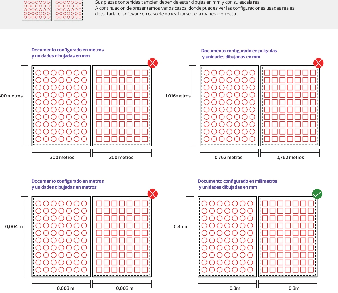
All files must be at 1:1 scale and in millimetres, inside the rectangle that represents the sheet. A 0.6 × 0.8 m sheet is drawn as 600 × 800 mm with the document set in mm.

The quoter shows the sheets it detects and their size. If a size is wrong you can type the real length of one rectangle and the whole file rescales proportionally (not sheet by sheet). If in doubt, fix the file in your software and upload it again.

Delete everything outside the rectangles. Blocks, dimensions, dotted lines, hatches and non-outlined text are not recognised. Notes go on the Comments layer.

Original diagram: 6. Size, units and scale (Spanish labels), 1
Original guide illustration with Spanish labels.

7. Strokes, shapes and lines

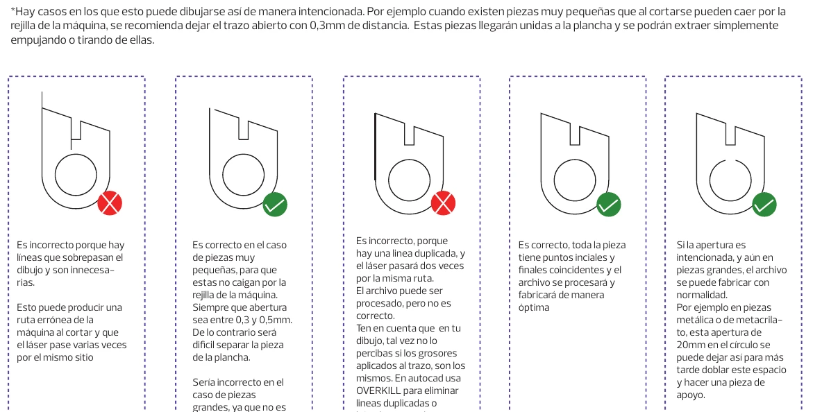
Check there are no overlapping or duplicated lines: you may not see them, but the laser would pass twice and the price would go up. In AutoCAD, OVERKILL removes duplicates.

End points must meet the next line exactly: neither overshoot nor fall short. Exception: very small parts (from 7 × 7 mm or 7 mm diameter) can be left open by 0.3–0.5 mm so they stay attached to the sheet and don't fall through the bed.

Original diagram: 7. Strokes, shapes and lines (Spanish labels), 1
Original guide illustration with Spanish labels.

8. Machines and laser cutting capabilities

We have more than 10 laser machines for metal and non-metal materials. The quoter selects the most suitable one automatically and limits each material to its available sizes and thicknesses.

Kerf (tolerance): +0.15 mm in metals and +0.1–0.35 mm in non-metals. Largest sheet: 3 × 1.5 m, although the limit is usually the sheet size of the material. Thickness: from 0.05 mm up to 10 mm in metals and 30 mm in non-metals.

9. Laser cutting limitations

Every process has limits. Keep to them and the result will be excellent; if you want to push them we will try, but cannot guarantee it. Designs with many cuts close together can lose quality: if in doubt, contact us.

The thicker the material, the wider the kerf: about 0.1 mm in thin materials up to 0.5 mm in thick ones. For press-fit parts without glue or welding, prototype before a series.

All values are approximate and not binding: each material behaves differently under the laser beam.

Original diagram: 9. Laser cutting limitations (Spanish labels), 1
Original guide illustration with Spanish labels.
Original diagram: 9. Laser cutting limitations (Spanish labels), 2
Original guide illustration with Spanish labels.

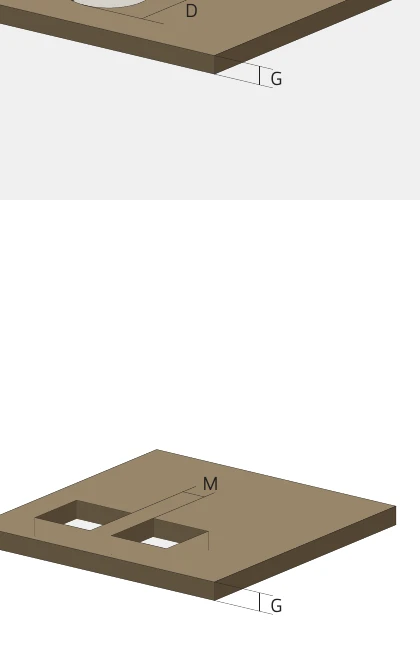
9.1 Minimum hole diameter (approx.)

Thickness (mm)Kerf (mm)Non-metals (mm)Metals (mm)
0.1–0.250.050.250.25
0.5–10.10.250.5
1.5–1.90.120.251
2–2.50.150.251
3–40.20.252
4–50.250.253
6–70.270.255
8–100.30.256
11–120.330.25—
12–150.350.25—
16–200.40.25—
21–250.450.25—
26–300.50.25—

9.2 Minimum distance between holes (approx., reference MDF)

Thickness (mm)Kerf (mm)Non-metals (mm)Metals (mm)
0.1–0.250.050.51
0.5–10.111
1.5–1.90.1211
2–2.50.1511
3–40.21.52
4–50.2522
6–70.2722
8–100.333
11–120.334—
12–150.354—
16–200.45—
21–250.456—
26–300.57—

9.3 Minimum part diameter (approx.)

Thickness (mm)Kerf (mm)Non-metals (mm)Metals (mm)
0.1–0.250.0521
0.5–10.121
1.5–1.90.1221.5
2–2.50.152.52
3–40.233
4–50.2534
6–70.2745
8–100.358
11–120.336—
12–150.358—
16–200.410—
21–250.4512—
26–300.515—

Prices and thicknesses by material: Laser cutting in Valencia →

Next step

From the guide to your part

Upload your file for an instant price, start from an idea with the configurator, choose your material or tell us about your project.

Would you rather we looked at it together?

Tell us what you want to make. We advise you on material, process and finish, and send you a tailored quote.

Ask about my project

We answer your doubts

Frequently asked questions

Which file format is best for laser cutting?

DXF, as it is the most universal and compatible. We also accept SVG, EPS, AI, DWG and PDF; for AI, SVG and PDF, check the detected dimensions.

Can I send a JPG or PNG image?

Not directly: the laser needs vectors. The image must be vectorised first, or ask us to prepare the file.

What margin should I leave on the sheet?

10 mm free of parts around the edge, as that strip holds the sheet during cutting.

How much space should I leave between parts?

About 2–3 mm. If parts share cutting lines, delete overlapping lines so the laser does not pass twice.

Why must text be converted to outlines?

Because the software cannot read text entities or fills: text must be a closed polyline to be cut or engraved.

Can't find your answer? Write to us and we'll reply within one business day.